Room to grow.
The workspace can be adapted through cable lengths and anchor positions. A larger print volume does not require an equally long moving gantry.

Trimed technology
The motion platform behind our vision for versatile 3D printing. A lightweight print head, eight controlled cables and a workspace that adapts to the task.
01 / THE PRINCIPLE
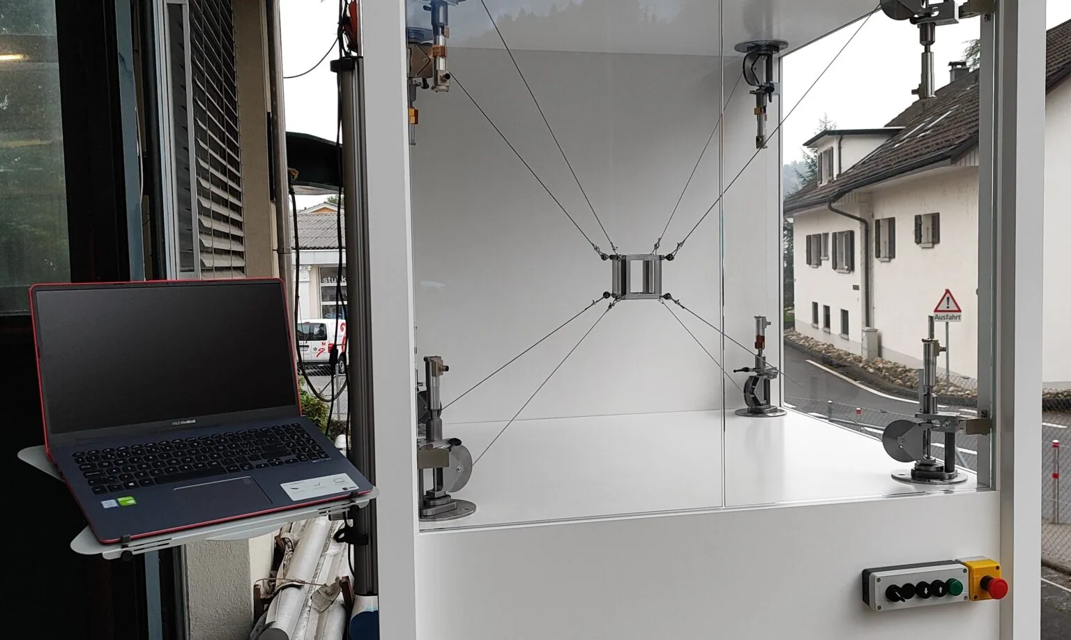
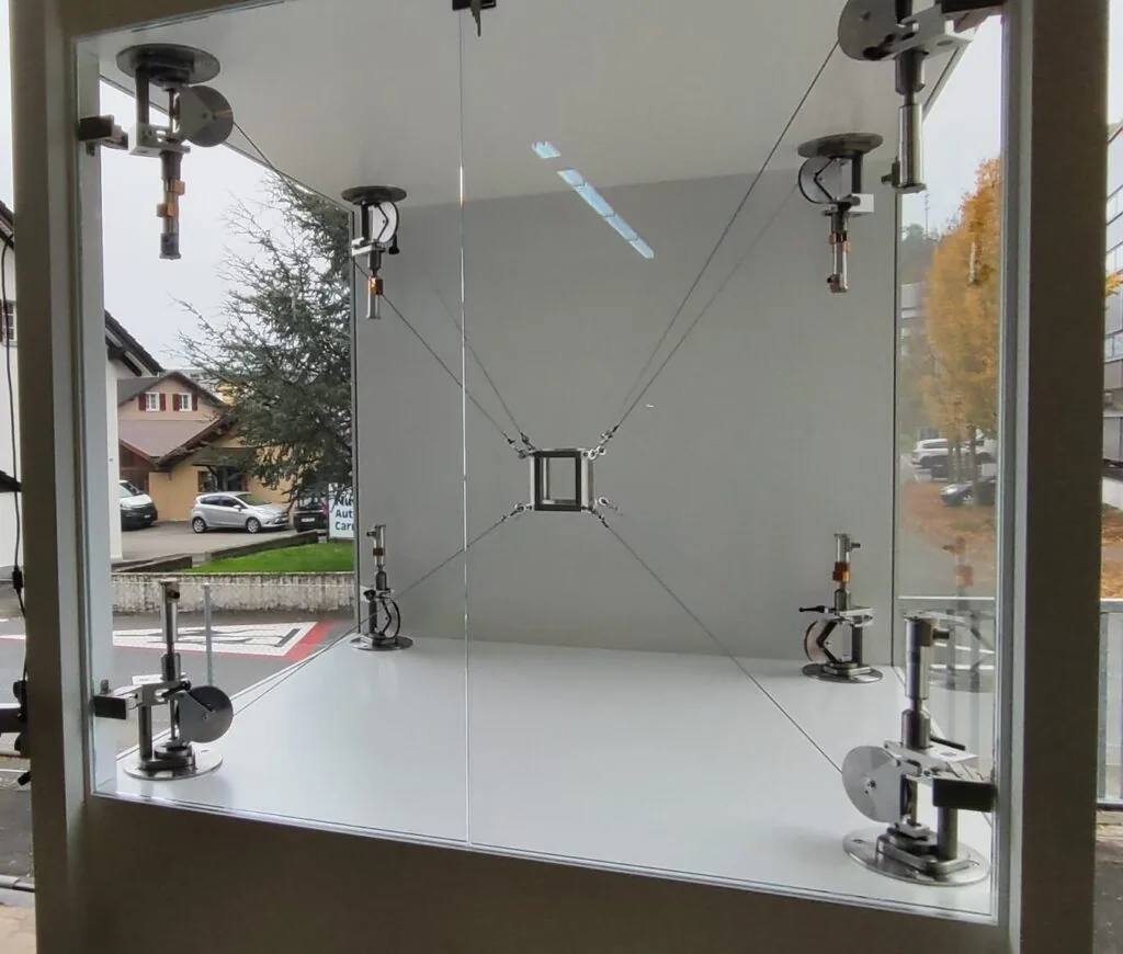
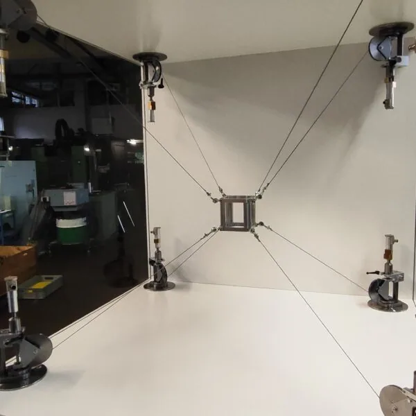
Coordinated changes in cable lengths position and orient the central platform. Six degrees of freedom describe its motion: three for position and three for orientation.
The workspace can be adapted through cable lengths and anchor positions. A larger print volume does not require an equally long moving gantry.
The drives remain outside the moving print head. Its low mass creates potential for high accelerations.
The concept envisages removable components, including the cables. For biomaterials, fast reprocessing in a sterilisation bath is a development goal.
Achievable dynamics and accuracy depend on design, cable tension, calibration, material supply and process. The sterilisation concept must be validated for medical applications.
CABLE ROBOTICS / INTERACTIVE PRINCIPLE
Ready to moveIllustration of the principle with example movements, not a simulation of an actual machine. Design, cable tension and accuracy are specified for each application.
02 / TECHNICAL OVERVIEW
The cable printer's key specifications at a glance. The actual workspace, tool and performance values are matched to the intended process.
| Parameter | Description |
|---|---|
| Cable guidance | 8 individually controlled cables |
| Moving platform | Print head on a central cable-guided platform |
| degrees of freedom | 6: three for position and three for orientation |
| Position & orientation | X, Y, Z plus roll, pitch and yaw; travel distances and angular ranges depend on the configuration |
| Reference working volume | 500 × 500 × 500 mm (X × Y × Z); variable according to application requirements |
| Printing accuracy | Down to 0.1 mm; dependent on configuration, material and printing conditions |
| Geometric reference volume | 125 litres (0.125 m³), calculated from 500 × 500 × 500 mm; the usable print space depends on cable geometry and tool access. |
| Cable drives & installation | Stationary drives outside the moving platform. The future enclosure concept places concealed drives and cable outlets inside the machine. |
| Cable forces & workspace | The eight cables guide the platform under tension. Permitted print space, tool load and acceleration are designed together with the anchor geometry. |
| Referencing & calibration | The design accounts for anchor positions, effective cable lengths and the offset between platform and nozzle tip. Enlarging the workspace requires appropriate calibration. |
| Material supply | A lightweight external material supply is proposed for the design. Filament routing, feed force and additional forces on the print head are matched to the material. |
| Tool changes | A modular print-head mount is proposed: plastic extrusion first, followed by separate dispensing heads for suitable biomaterials. Each process receives its own parameter settings. |
| Scaling | Adaptation of cable lengths, anchor positions and supporting structure; drives sized for load and dynamics |
| Moving mass | Central platform and print head; the drives remain at the external anchor points |
| 3D data formats | STEP and STL in the described software concept |
| Process functions | Slicing, printing control, monitoring and scanning |
| Operation | User-friendly control software, display and touch controls; adjustable print parameters |
| Interfaces | APIs and Ethernet via RJ45; specific API functions and integration scope depend on the configuration |
| Plastics | PLA, PETG, PA6 and PA12, plus further plastics; print head and material supply matched to the material |
| First printing process | 3D plastic printing; print head, material supply and process parameters are designed together |
| Biomaterials | Biocompatible hydrogels, cell cultures and biomedical materials as the intended material range for medical development |
| Dismantling & reprocessing | Removable components including cables; reprocessing in a sterilisation bath is envisaged for suitable biomaterial processes |
| Power connection / basic | 230 V AC · 6 A as the basic specification |
| Power connection / industrial | 230 / 400 V AC · 16 A, depending on the industrial version |
| Patent applications | Comprehensive patent applications for the kinematic chain of the Trimed cable robot in 39 countries; the applications are confirmed. |
Trimed states printing accuracy down to 0.1 mm for the cable printer. Achievable part quality depends on workspace, calibration, material and print parameters. Test conditions and tolerances are defined for the specific application.
Positioning accuracy describes deviation from a target position. Repeatability describes how consistently a position can be reached again. The accuracy of a printed part also depends on the printing process and material.
PLASTIC PRINTING / FIRST PLANNED APPLICATION
The material range includes these plastics and further materials. Nozzle diameter, layer height, temperature control and material supply are adapted to the selected material.
BIOMATERIALS / MEDICAL DEVELOPMENT
Biocompatible hydrogels, cell cultures and further biomedical materials are part of the intended development scope. Material suitability, sterilisation and regulatory evidence are steps towards a medical application.
The power connections describe the electrical supply. Actual energy consumption depends on the print head, heating, drives and operating state. The machine is designed for energy-efficient operation.
DESIGN EXAMPLE / PLASTIC PRINTING
The following values are plausible planning assumptions for an initial plastic configuration, not confirmed performance specifications. The final design will be matched to the print head, material and prototype testing.
| Parameter | Description |
|---|---|
| Printing process & supply | FFF / FDM with 1.75 mm filament as the assumed initial plastic configuration. |
| Interchangeable nozzles | 0.4 / 0.6 / 0.8 mm. Smaller nozzles for fine contours, larger nozzles for wider paths and greater material deposition. |
| Layer height | 0.10–0.30 mm with a 0.4 mm nozzle; 0.20–0.40 mm with 0.6 or 0.8 mm nozzles. Layer height is a process setting, not a measure of printing accuracy. |
| Print head / temperature target | Up to 300 °C as a design target for the plastic configuration; actual printing temperature follows the material data sheet. |
| Print bed / temperature target | Heated, interchangeable print surface up to 120 °C as a design target. Match the adhesion surface and thermal uniformity to the part. |
| Printing speed | 50–150 mm/s as a planning range. The usable value depends on geometry, extrusion capacity, layer height and material. |
| Travel speed | 150–300 mm/s as a planning range for moves without material deposition; within the permitted cable and workspace limits. |
| Acceleration | 1–3 m/s² as an initial design range. Cable tension, vibration behaviour and print quality determine the subsequently validated motion profiles. |
| Moving mass | 0.5–1.5 kg as a target range for the platform and plastic print head, excluding separately mounted material supply. |
| Material conditioning | Provide dry feeding and enclosed storage for moisture-sensitive materials. PA6 and PA12 receive material-specific drying and temperature profiles. |
| Enclosure & cooling | An enclosed build space is proposed for reproducible process conditions, with controlled part cooling. Assess the need for additional chamber heating for each material. |
TECHNICAL DEVELOPMENT CONCEPT
The following functions describe the proposed further development of the platform.
01 / MOTION CONTROL
Proposed control concept: synchronised drives with position feedback, cable-tension monitoring and motion profiles matched to the tool load.
02 / OPERATION & API
Display and touch as the central operator interface. Proposed software extensions: material profiles, print preview, progress, temperature and status displays, plus job and status exchange through API and Ethernet.
03 / QUALITY & ACCESS
Proposed for further development: homing, tool-offset calibration, temperature monitoring, emergency stop and monitored access doors. Accuracy and repeatability are assessed separately at defined positions and using test parts.
TECHNICAL CONFIGURATION
Workspace, extruder and motion profiles are brought together for the application. Together, we define the material, part geometry, quality requirements and appropriate machine configuration.
03 / SCALABILITY
Longer cables and adapted anchor positions can enlarge the workspace. This offers potential to expand the print volume without proportionally enlarging all moving axes.
Frame stiffness, drives and cables are matched to the required load and dynamics. Economic potential is part of development; costs and performance are assessed for each project.
The described software concept includes STEP/STL processing, slicing, printing control and scanning. Data format, software version and process are agreed for a specific application.
04 / DATA & PRINTING PROCESS
Geometry preparation, print path and cable movement work together. The previous website describes an integrated software process chain.
A 3D model is the starting point for preparation. Scan data can provide an additional basis for the required geometry.
The model is divided into layers and toolpaths. Layer height and material deposition depend on the print head and material.
The desired platform pose is translated into suitable cable lengths. Motion planning must account for geometry and permissible cable forces.
Printing control, monitoring and scanning are described in the software concept. Their scope is specified for the application.
CABLE KINEMATICS DESIGN
Cables transmit tensile forces. The geometrically reachable position alone is therefore insufficient for design: the platform must also be guided with permissible cable tensions under the intended loads.
Anchor geometry, cable elongation, calibration and tool load influence motion. The supporting structure and process control are designed for the required dynamics and precision.
Background on the cable robot principle · Fraunhofer IPA ↗05 / APPLICATIONS
FIRST PLANNED APPLICATION
The first application focus is 3D plastic printing. Prototypes, individual geometries and larger parts provide the basis for developing the platform and printing process.
Explore plastic printingRESEARCH & DEVELOPMENT
In parallel with plastic printing, we plan to develop patient-specific bone replacement structures. This requires suitable biomaterials, validated processes and regulatory evidence.
Explore the medical visionOPEN TECHNOLOGY PLATFORM
Cable robotics provides a basis for further additive manufacturing and handling tasks. Tools, material supply and control are adapted to the specific application.
Discover the platform06 / DEVELOPMENT INSIGHTS
07 / DESIGN STUDY / OUTLOOK
A possible next generation of the Trimed cable robot: the existing cable architecture, reimagined for operation, access and industrial design.
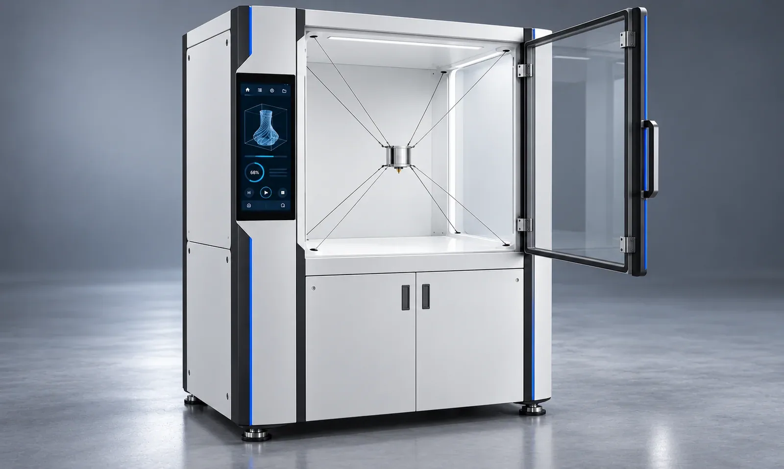
An integrated touchscreen brings controls into a modern interface, with a workspace view, print path and process status.
The sheet-metal enclosure fully integrates the cable drives. The eight cables enter the printing chamber through discreet guide openings; motors and cable drums remain concealed.
A transparent opening access door and service doors in the lower cabinet provide access. The roughly person-height, floor-standing machine offers an accessible workspace for standing operation.
The enclosure, user interface and access concept show a design proposal; the technical implementation will be defined during development.